
This is going to be a 2-series tutorial, where in the first post you'll make the lego piece (part) and at the second part of the tutorial you'll assemble the lego pieces together (assembly).
1. Open up SolidWorks on your computer. After it loaded, a screen like below should be seen.


7. Now click on the top surface of the solid (shown in blue in image below), right click on it, and select Sketch.

8. Press space bar, and choose Normal to, such that that surface is now facing you. Draw two circle, randomly, like shown below. Left click on the left circle. While holding ctrl button, left click on the right circle. On the left tab (Properties), select equal.
Note: Holding the ctrl button allows you to do multiple selection.
By adding equal relations on the two circles, now they will have same radius.

9. Now select the center of the left circle.

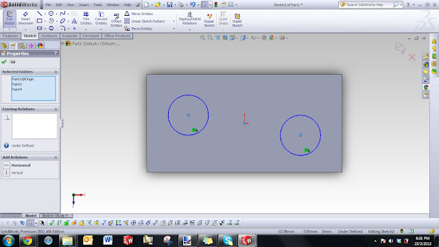
11. On Sketch Ribbon, click on Smart Dimension and give dimension to the circle as shown below. Notice after giving all these dimensions, the circle color should change from blue to black.

12. Same like previously, now we need to extrude the circle (See step 6 if you forget how to extrude). On the left tab, Select Blond and extrude for 5 mm. Click the OK button to confirm. The shape of the LEGO piece started to form.

13. Now select the bottom face (shown in blue in image below). Right click and select "sketch".


16. You should see the result as something like shown below.

17. Same step as previously, draw four circles (two of them to be concentric to each other), and give dimensions as shown below. Note that I started to skip few details as you should have done previously.

18. Click Insert => Boss/base => Extrude. On the Boss Extrude tab on the left side, select "Up To Surface" for direction 1, and select the pink surface shown in image below as the reference surface.

19. Now select the surface as shown below in blue, right click, and select sketch.

20. Draw a random rectangle and give dimension as shown in image below.

21. Draw two circles, concentric to the circle we extruded previously like shown below (shown in blue color). Alternative method is to use "Convert Entities", and select the outer edge of the circles.


23. Likewise, do the same thing on the unwanted part of the sketch on the right side.


26. Using Trim tool, trim away unwanted sketch like shown in image below.


28. Click Insert => Features => Chamfer. On the Chamfer options box on the left side, enter 1 mm for the chamfer distance and the angle to be 45 degree (default is set at 45 deg), and select all four outer corners of the Lego piece. Click OK to finalize the feature.

29. Using the same setting, insert another chamfer at all four inner corner of the piece.

30. Click OK to finalize and create the chamfer. Now your Lego piece should look something shown below. You're almost reaching the end =)


Continue to the second part of the tutorial here.
1. Open up SolidWorks on your computer. After it loaded, a screen like below should be seen.

2. Click File => New => Parts. A display as shown below should be seen. Note on the model tree (left tab), a default front, top, and right plane and the origin is automatically created.

3. Right click on the "Top Plane", and choose sketch (on the left side of the glasses logo). By doing this, you're going to create a 2D sketch on the top plane.

4. After doing step no. 3, you will notice that the ribbon on top is now automatically set to "Sketch" ribbon. Press spacebar, and select "Normal To". Notice that now the top plane is now aligned to your computer screen. Choose the rectangular icon from the ribbon, and draw arbitrary rectangular as shown below.

5. Now click on "Smart Dimension" from the sketch ribbon. Click on the top line on the left followed by line on the right, and enter 24 mm for the value. This step is used to give dimension to the sketches. Give all dimension to all the lines so that it look like what is shown in figure below. Note that all the line has turned from blue to black color.

6. After completing the sketch, now its time to extrude the sketch. Click insert => Boss/base => Extrude (Alternatively, you can click on Features tab and click Boss Extrude). Notice that Boss extrude tab now appears on the left side of the screen. Select Blind on the drop down menu of Direction 1, and enter the value of 10 mm. See image below for reference. After all these have been done, click on the green thick button (lets call it OK button) to confirm the feature. Now you have a solid block =)

7. Now click on the top surface of the solid (shown in blue in image below), right click on it, and select Sketch.

8. Press space bar, and choose Normal to, such that that surface is now facing you. Draw two circle, randomly, like shown below. Left click on the left circle. While holding ctrl button, left click on the right circle. On the left tab (Properties), select equal.
Note: Holding the ctrl button allows you to do multiple selection.
By adding equal relations on the two circles, now they will have same radius.

9. Now select the center of the left circle.

10. While holding ctrl button on your keyboard, select the center of the right circle. On the left tab (Properties), select Horizontal. Observe that now the two circle is aligned horizontally.

11. On Sketch Ribbon, click on Smart Dimension and give dimension to the circle as shown below. Notice after giving all these dimensions, the circle color should change from blue to black.

12. Same like previously, now we need to extrude the circle (See step 6 if you forget how to extrude). On the left tab, Select Blond and extrude for 5 mm. Click the OK button to confirm. The shape of the LEGO piece started to form.

13. Now select the bottom face (shown in blue in image below). Right click and select "sketch".

14. Draw a random rectangular and using the "Smart Dimension", give a dimension as shown in picture below.

15. Now select Insert => Cut => Extrude. On the Cut Extrude tab on the left side, select blind with a distance of 9 mm.

16. You should see the result as something like shown below.
Now, select the inner surface as shown below in blue, right click, and select Sketch.

17. Same step as previously, draw four circles (two of them to be concentric to each other), and give dimensions as shown below. Note that I started to skip few details as you should have done previously.

18. Click Insert => Boss/base => Extrude. On the Boss Extrude tab on the left side, select "Up To Surface" for direction 1, and select the pink surface shown in image below as the reference surface.

19. Now select the surface as shown below in blue, right click, and select sketch.

20. Draw a random rectangle and give dimension as shown in image below.

21. Draw two circles, concentric to the circle we extruded previously like shown below (shown in blue color). Alternative method is to use "Convert Entities", and select the outer edge of the circles.

22. Now from the Sketch ribbon, select "Trim Entities", and select "Power Trim" from the Trim option tab on the left side. Left click on the mouse, hold, and drag the cursor through the unwanted part of the sketch as shown in image below.
Note: This step, how to use Trim, is a very important step. Make sure you understand how to use the Trim tool.

23. Likewise, do the same thing on the unwanted part of the sketch on the right side.

24. Using the same technique as step 18, perform an Boss Extrude, Up To Surface, and the pink surface shown below as the reference surface.

25. Now do the same thing, sketch two vertical rectangles and using Smart Dimension, complete the sketch as shown below.

26. Using Trim tool, trim away unwanted sketch like shown in image below.

27. Similarly, perform Up To Surface Boss Extrude until the bottom surface of the Lego piece. If you follow all the steps correctly, you should have a rough shape of a Lego piece like shown below. Now what is left is just some finishing to make it look more realistic =)

28. Click Insert => Features => Chamfer. On the Chamfer options box on the left side, enter 1 mm for the chamfer distance and the angle to be 45 degree (default is set at 45 deg), and select all four outer corners of the Lego piece. Click OK to finalize the feature.


30. Click OK to finalize and create the chamfer. Now your Lego piece should look something shown below. You're almost reaching the end =)

31. Insert chamfer again, but this time enter 0.30 mm for the chamfer distance, leave the angle at default 45 degree. Select the top and bottom edges of the Lego piece (shown in dotted blue line in image below). Click OK to proceed.

32. Now you have reached the end of the first tutorial part. Your Lego piece should look like the real Lego piece as shown below. Congratulation on your completion!


